The 3D printing process has a unique capability of controlling the infill or material density of the printed part with respect to the actual CAD data. The actual part volume may be lesser than the CAD part volume figures. This helps in achieving optimized strength, weight & structure parameters which can be increased or decreased according to the requirement. In comparison to other manufacturing processes, 3D printing has the capability which allows the designer to control the two key parameters such as wall thickness & infill density. Infill exists within the periphery of the outer wall. The infill parameters can be controlled by slicers software when the model is converted into G-codes. Further, infill has two key parameters i.e., infill density and infill pattern. In this article, we’ll discuss the various types of infill patterns & infill density in detail.
3D printing & conventional manufacturing
Conventional manufacturing like CNC machining where the part is carved out substantively of the solid stock by the cutter as per the CAM profile. There’s no way to control the solid density hence the final geometry is solid from the inside.
In formative processes like injection molding, the hold plastic in semi-solid form is forced into the empty cavity of the mold. There’s no way to control the solid density due to the type of the process except the ‘Gas-assisted injection molding’ which is capable of hollow parts by the application of high-pressure gas.
Another formative process is sheet metal fabrication forms the part by bending the metal sheet in pre-fabricated dies. The formed part takes the shape of the die and there’s no way to alter the solid density of the part.
Infill density percentage
Infill density means the completeness of the inside of the solid part. This is usually defined as the percentage(0~100%) of the total solid volume in the slicing software. Zero means hollow from the inside and just outer perimeter walls. The part will be very weak in strength and not suitable for functional testing. The 100% infill part is completely solid from the inside hence a fully dense part but costs higher. Apart from weight, print duration and material quantity consumed are also impacted by the infill settings. So, the strength and the weight of the part are the combinations of infill density but also the material type, layer height and build direction. Some advanced software allows different infill setting within the same design means you can have 30% infill density in one section and 75% density in another section within the same part.

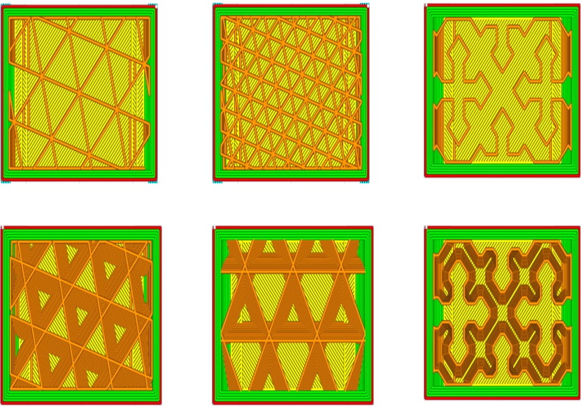
Infill percentage and different types of infill patterns
Which infill pattern and percentage is best for my requirement?
For most common prints, 20~50% infill density is fine where the designer doesn’t want the part to be very strong just for evaluation purposes. Lower infill densities reduce build times and consume less material. For actual functional requirements, densities could be set according to the requirements for example, 65% density is more than sufficient to satisfy the strength requirement for some specific application. The designer is still able to print part 35% hollow from inside saving time and cost than the same part made by conventional manufacturing.
Types of infill pattern
Infill patterns are the design of the internal geometry of the density from just plain lines to complex layouts. Infill shapes affects the print durations, part strength, weight & flexibility. Hence, the decision of pattern selection depends upon the application requirements.
- Honeycomb
- Grid
- Triangles
- Tri-hexagon
- Octet
- Gyroid
- Cubic
- Cubic-subdivision
- Concentric
- Cross
- Cross-3D
Honeycomb
As the name suggests, the honeycomb pattern enhances compressive strength in the Z direction and provides a good visual appeal. The pattern is good for parts requiring moderate strength with reduced print times and material consumption.

Honeycomb infill pattern
Grid
As the name implies, two-dimensional patterns are generated like lines providing strength in two dimensions. The patterns consume moderate material and average print times.

Grid infill pattern
Triangles
A two-dimensional mesh pattern has more strength when the force is applied normally to the surface or face. This pattern is usually good for those designs where moderate functional strength is required.

Triangle infill patterns with 20% & 50% densities
Tri-Hexagon
This pattern contains an array of lines in three directions of XY plane generation hexagonal shapes with triangles in the middle. And provides strength in two directions which is good for general functional requirements.

Tri-Hexagon infill pattern
Cubic & Cubic-subdivision
- Cubic - This pattern contains a three-dimensional cubic layout one above the other in slanted form.
- Cubic-subdivision - This alteration of cubic pattern consumes less material resulting in material cost savings.

Cubic & Cubic-subdivision infill patterns
Octet
It is like a cubic pattern with a square shape instead of a slanted triangle. This pattern spreads out in three dimensions, is visually good and imparts good strength. However, this pattern consumes slightly more material and print time.
Gyroid
This pattern is perhaps the most unique pattern and strangest among all other patterns. It consists of non-regular concave curvatures with intersecting paths resembling waves proving maximum strength in all directions. This pattern fulfils the criteria for designs that require high compressive strength in multiple directions.

Octet & Gyroid infill patterns
Concentric
This pattern somewhat replicates the outer perimeter of the part resembling the formation of waves when a stone is thrown into the water.

Concentric infill patterns
Cross & Cross 3D
- Cross - It’s a two-dimensional pattern creating a good-looking pattern. Gaps between the pattern add some flexibility to the design allowing it to twist and bend.
- Cross 3D – It is the same as cross however the line moves at angles resulting in the addition of extra rigidity to the physical part.

Cross & Cross 3D infill patterns
Suggested Infill Settings
|
Print type |
Infill pattern |
Infill density |
|
General parts |
Grid, Triangles or Tri-hexagon |
20~25% |
|
Functional parts |
Cubic, Gyroid or Octet |
>50% |
|
Model prints |
Lines or Zig-Zag |
20~30% |
|
Flexible designs |
Concentric, Cross or Cross 3D |
0~100% |
Other factors
- Infill line direction – The default setting is 45˚ to let the extruder fill the material at a maximum rate saving considerable print time. It can be changed according to the requirement in order to increase strength or flexibility in the physical part.
- Gradual infill – The designer can set larger densities towards the outer walls. This results in less material consumption and helps in maintaining the optimal strength and stiffness of the part.
- Gradient infill – Gradient infill provides denser infill patterns towards the top of the part than the bottom. This ensures the material is deposited where it needs the most making the top end stronger than the other end.
Conclusion
3D printing is the only manufacturing technology that allows you to vary the internal density of any design resulting in the creation of highly optimized physical parts. Certain special software like the one offered by ntopology offers an even more diverse set of infill designs (lattice structures) along with topology optimization which isn’t available in other freely available software. Not only infill densities but the right selection of pattern is key to optimal application performance of the design which could be further achieved by using special software catering to the requirements. Apart from density & pattern, creative or art patterns allows you to explore the artistic side of various patterns. In future, we’ll see more innovation in infill density areas with the increasing adoption of Additive manufacturing across industries.
Blog created by - 3D SculpLab Team