Modern manufacturing works by the way of creating a digital design using CAD software and digital data control and drives the fabrication machines to create the final shape. A large variety of digital machines are available from a small desktop level to a very large special fabrication set-up. The digital shape is prepared by the CAD software and then that CAD file is transferred to a fabrication software also known as CAM (computer-aided manufacturing). CAM output becomes the input data for the various fabrication set-ups like subtractive machining, 3D printing & shape forming machines (pipe bending) etc.
In today's time when professional-grade manufacturing becoming more affordable and accessible, anyone having knowledge of product design could fabricate it easily. Digital manufacturing is plugging the gap between the product design and its fabrication, enabling designers and engineers across the industrial spectrum to create innovative products from a simple prototype to mass production.
Digital fabrication workflow
3D Data generation
- CAD model – A CAD model is generated by the product designer using specialized CAD software representing the digital image of the designer’s imagination. CAD data go thru multiple iterations and reviews before it is ready for further processing. This data act as input data to digital manufacturing machines in formats compatible with the fabrication setup. The exported format creates a triangulated shape with faces on the surface, vertices, and vectors normal to the surface. Some formats capture information like colour, and surface finish which the fabrication machine could read saving the set-up time.
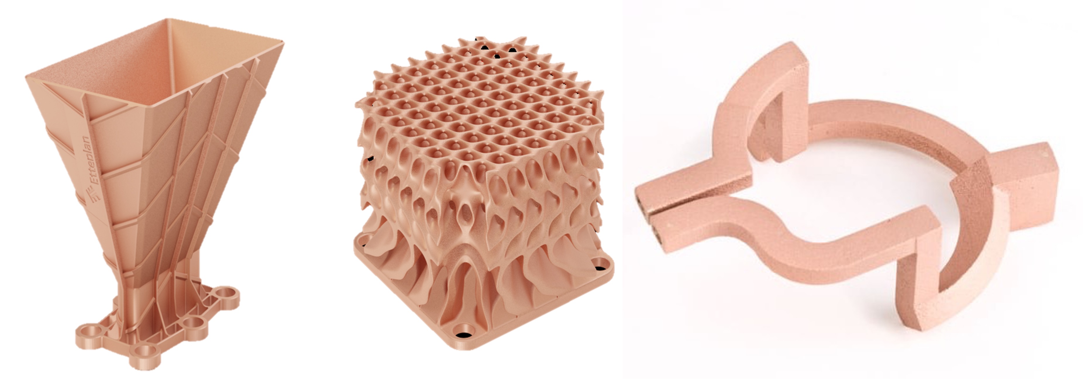
- CAE Analysis – Generated design file is then analyzed by a CAE (Computer-Aided Engineering) tool to check if the part can perform in the real-world application as desired. Design topology is optimized by removing the extra material if the part is to be manufactured by a 3D printer.
Digital manufacturing pre-processing
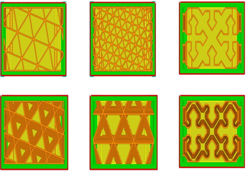
- Support structure generation – If the design is to be made by 3D printing, then the technician needs to study the build orientation, support structure placement, and surface adhesion type. Printing layers are generated by the slicing software which generates the virtual manufacturing model with tool paths. Manufacturing-related parameters and specific instruction settings are added to the manufacturing model.
- Part holding set-up – Part holding fixtures for the models which are supposed to be carved out of the metal block are created in the CAD software and added to the manufacturing simulation software along with the original shape. The simulation tool will identify and avoid tools hitting the fixture during tool path generation.
- Post-processing set-up – Post-processing set-ups are created if the physical part goes for surface, heat treatment or assembly operation in case of multiple parts. This will ensure correct orientation/alignment according to the requirements.
- Digital fabrication – Manufacturing simulations are done on the digital part before sending the data to the machine. Virtual tool paths are generated and build orientation and tool movements are analyzed by the technician. If needed, the design is modified to suit manufacturing requirements based on the simulation feedback. Special settings related to the manufacturing needs are added to the simulation file. When all the simulation-related activities are completed, then the file is exported in machine-readable codes or directly uploaded by the software to the target machine.

Digital thread: Digital manufacturing workflow
Digital Fabrication devices
Additive manufacturing
- FDM/FFF (Fused Deposition Modelling / Fused Filament Fabrication) – Melted wire plastic is extruded from the nozzle and its deposition on the build plate is spatially controlled. Layer by layer this process repeats creating a physical part however the accuracy and surface resolution are not the best in comparison to other plastic 3D printers. FDM is good for making basic functional prototypes and proof of concepts at the lowest cost.
- SLA (Stereolithography) – Photosensitive liquid resin is cured by the spatially controlled scanner beam or high-resolution projected image. The curing process creates a cross-linked solid layer by layer ultimately creating physical parts. SLA produces parts with a high surface finish and accuracy. SLA is most suitable for general prototyping and short-run production where aesthetics and accuracy are the key requirements.
- Selective laser sintering (SLS) – SLS creates parts by sintering the polymer or metal powder with a high-intensity laser beam which fuses the powder particles into a solid form. Repeating this process layer by layer generates a solid part. SLS parts have excellent mechanical properties and strength comparable to the injection-molded plastic part.
CNC Machining
- CNC machining – CNC machines work by carving out a part out of a metal or plastic block with a rotating tool moving spatially or linearly(CNC lathe). CNC machines start from a small size lathe to a very large multi-axis machining centre. CNC machining is suitable for creating parts where a high surface finish and close tolerances are needed.
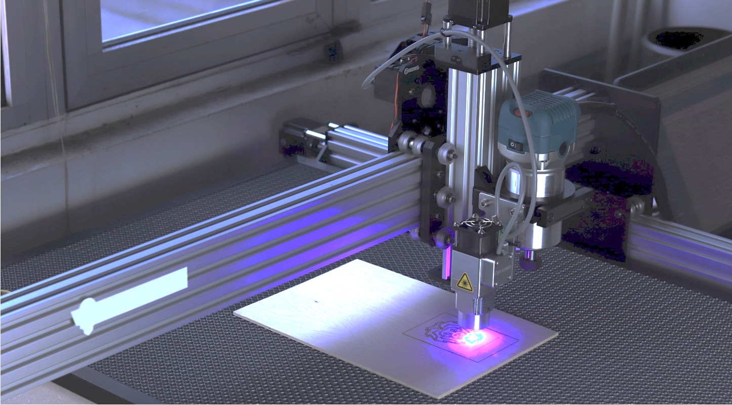
- CNC laser cutting – High-intensity laser beam is used to cut or engrave on metals, plastics and wood. These cutters are cost economical, quick and easy-to-use machines. In the same line of CNC machines, a laser beam travels spatially controlled by the computer. 2D vector drawings are the input to the machine controller which is often clubbed with the main CAM software.
- CNC pipe bending – Pipe routings can be easily created by a CNC pipe bending machine. Just create the pipe layout design in CAD and the CAM software will generate the machine codes for bending. AC plumbing of an automobile or any other industrial application pipe routings are made by a pipe bending machine.
- CNC water jet cutting – High-pressure water jet mixed with abrasives can cut thru any material. Water jet cutters can cut thru thicker sheets of metal than laser cutters. They can even cut thru harder metals which are generally difficult to cut by other means to get the exact shape.
Inspection & Verification
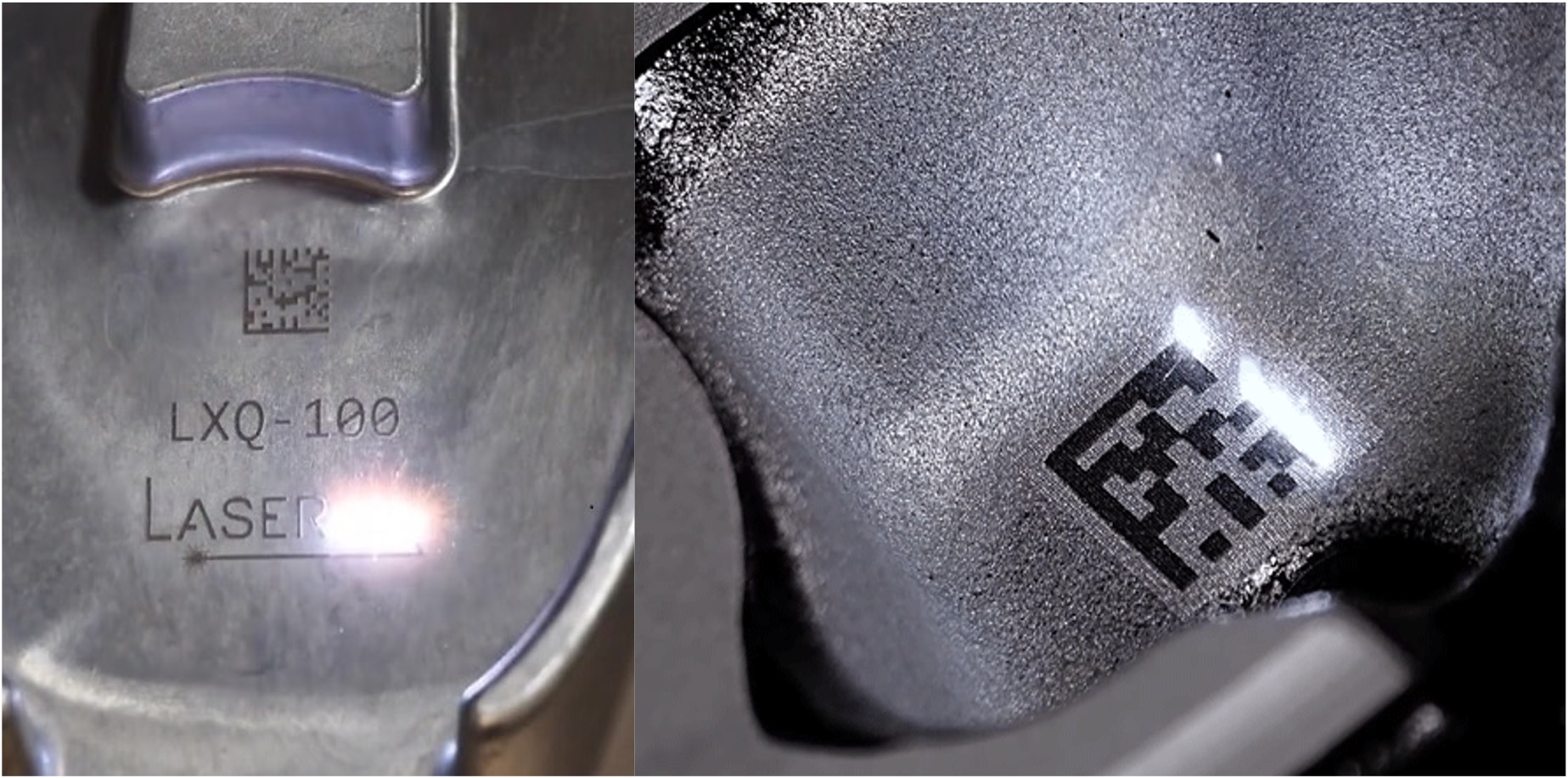
The physical part is inspected by the technician by using various means like CMM or laser scanning. At this stage, the digital twin is matched with inspection data and then the manufacturing file and other process parameters are fine-tuned thru continuous feedback. Part is automatically rejected if not meeting the desired design tolerances.
End of life
Every product has an expiry date or is discarded by the user. Parts are designed in a way that their various smaller components can be recycled easily instead of dumping into a landfill. Recycling not only saves the environment from pollution but also lowers the cost of input materials.
Conclusion
All the stages right from the design conceptualization to the end of life are connected by a digital highway known as a digital thread. This means feedback received at every stage is sent back to the digital twin and the virtual model is updated accordingly in real time. Digital thread not only enhances the quality of the product but reduces the chances of failures in real-world usage.
Blog created by - 3D SculpLab Team