What is Geometrical Dimensioning and Tolerancing?
Geometric Dimensioning and Tolerancing (GD&T) is a global engineering language of symbols, used to efficiently and accurately communicate geometrical requirements for design features. It encourages designers to define a part based on its function (design intent) in the final product. ASME Y14.5M – 1994 is a globally accepted geometric dimensioning and tolerancing standard.

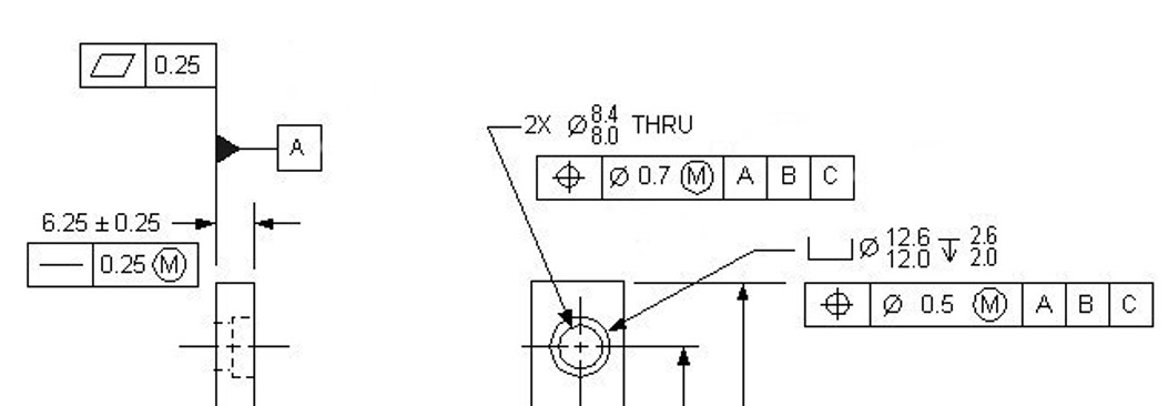
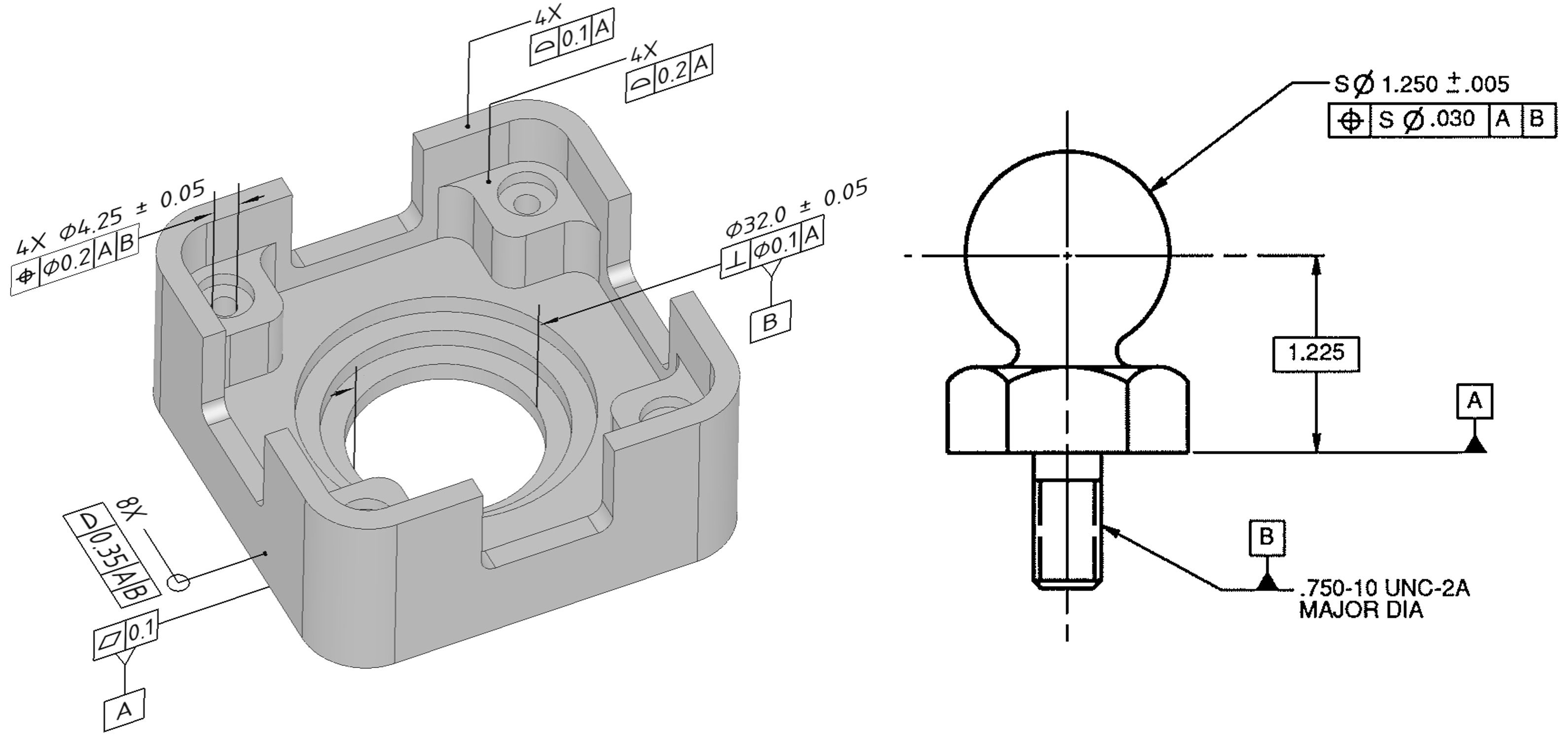
An example: Part dimensions using GD&T.
Types of tolerances
- Limit tolerancing
- Geometric tolerancing
Limit tolerancing –
- Tolerance can be specified only where a dimension is given.
- Gives an acceptable range of values of an individual dimension (limits of dimension).
- No provision to specify how flat a surface needs to be, or how much a hole can tilt relative to a surface.
- Induces problems related to ambiguity, guesswork and multiple interpretations of part drawing. Results in deviation from the design intent.
Geometric tolerancing –
- Separates the specification of tolerance from the dimensioning.
- Specifies a geometric region (tolerance zones), such as an area or a volume, in which the feature must lie in order to meet the design criteria.
- Communicates complex geometrical descriptions not possible otherwise in language. Allows more flexible and precise controls that relate directly to the form, fit and function and not just the size of the part, leading to a successful end product.
- Eliminates guesswork and enables mfg. according to design intent, thus reducing confusion, rejection, rework and loss of profits.
What is the feature control frame in GD&T?
- Basic sentences in GD&T are put in the form of a feature control frame panel.
- It captures the requirements for the feature to which it is aligned.
- Each feature control frame can state only one requirement/message. Only one set-up or gage for one FCF.
- Detail explanation of the Feature control frame is given below

Details of a feature control frame
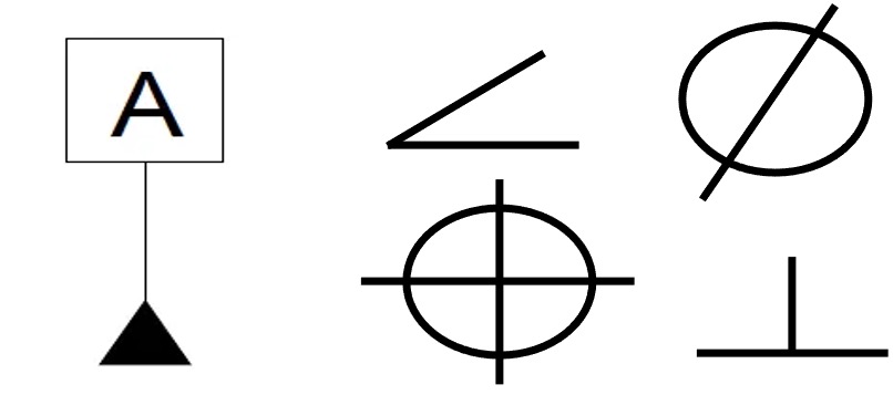
First section
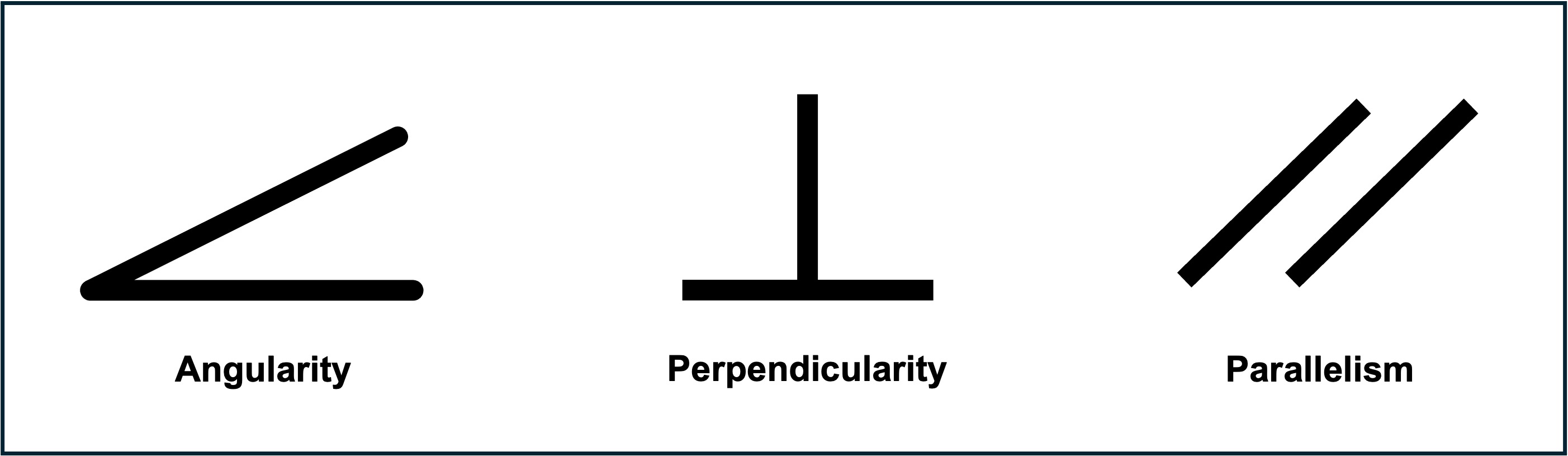
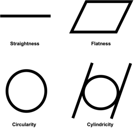
- Geometric characteristic symbol: Specifies the character to which the tolerance is to be applied.
- Example Flatness, angularity, profile, parallelism etc.

The first section - contains one of the 14 geometric characteristic symbols
Second section
- Symbol to specify the shape of the tolerance zone – This symbol precedes the tolerance and specifies the shape of the tolerance zone. For example, Ø specifies a cylindrical tolerance zone, and SØ specifies a spherical tolerance zone. If no symbol is given, the default shape is parallel planes, or a total wide zone (like in profile tolerance).
- Material condition modifiers – Features of size can be provided with bonus tolerances using these modifiers. If the feature being controlled is a feature of size, and no modifier is specified, the default is RFS.

The second section - contains actual tolerance, material condition modifier and other symbols
Third section
- Datum system – Specifies datums if applicable. They are significant according to their precedence in the FCF.

The third section - contains the datum reference frame
Other symbols in the FCF
- The symbols for projected tolerance zone, free state, tangent plane, and statistical tolerance always follow the material condition modifier.
- A new datum feature symbol has been introduced in ANSI Y14.5, 1994.

Other Datum symbols
What is Datum System in GD&T?
- Datum - A theoretically exact plane, point or axis from which dimensional measurements are made. Datums are points, lines, planes, cylinders, axes, etc. from which the location or geometric relationship of other part features may be established or related.
- Datum Feature - A datum feature is the actual component feature used (idealized) to establish a datum.
- Datum Feature Simulator - A datum simulator is a surface of adequate precision oriented to the high points of a designated datum from which the simulated datum is established.
- Examples: gage pin, block, and the surface of granite block.
- Diameter Symbol - Indicates a circular feature when used on the field of a drawing or indicates that the tolerance is diametrical when used in a feature control frame.
- The inspection equipment (or gage surfaces) used to establish a datum is the simulator.
- Datums are specified in the third compartment of the feature control frame.

Feature constrained within said tolerance with respect to datums A,B
- They are theoretically exact features (surfaces idealized to planes, axes etc.) from which dimensional measurements are made.

Example part: Surfaces are idealized to eliminate ambiguity about from where dimensions are to be measured
- But if both surfaces are idealized simultaneously, they may not be perpendicular to each other.

Precedence order in datum planes
- If we use a set of perpendicular datum references, either of the two positions could be right.

Without precedence order, either of these two could be the correct position. The final position depends on which side contacts first
- Thus, they are specified in an order of precedence governed by the part function.

Therefore, the first side to be pressed against one of the edges (in this case, datum A), will make contact at the two highest points. The part now has only one degree of freedom left, it can only slide back and forth along this edge. Once we butt the perpendicular side of the part with the corresponding straight edge (datum B), we have a completely constrained position and orientation.
What are Tolerance Zones?
- Defined according to the functional requirement of the part.
- Tolerance zones can be defined in GD&T instead of limits of dimension.
- These are geometric regions (3D or 2D) in which the feature must lie to be acceptable.
- Ensures closeness to real-world requirements
- Enables specifications (like conical tolerance zones) not otherwise possible in limit type dimensioning.

Tolerance zones
Advantages of GD&T
- Functional dimensioning philosophy
- Round Tolerance zones.
- Bonus tolerance by material condition modifiers.
- Datum system for clarity in inspection/fixture mfg.
- Reduces the need for drawing notes, and provides more wieldable language for specifications.
- Supports Statistical process control (SPC)
Created by - 3D SculpLab Team