What are Material condition modifiers?
- GD&T on holes (and shafts) provides a powerful tool for increasing inspection yield without trial-and-error fitting or binning.
- Used when the size of the feature interacts with its location.
- If ⓜ the symbol appears after the tolerance, then the specified tolerance holds only at maximum material condition.
- As the feature departs from MMC, the amount of departure can be added to the position tolerance.
- MMC is commonly used for clearance-type applications.

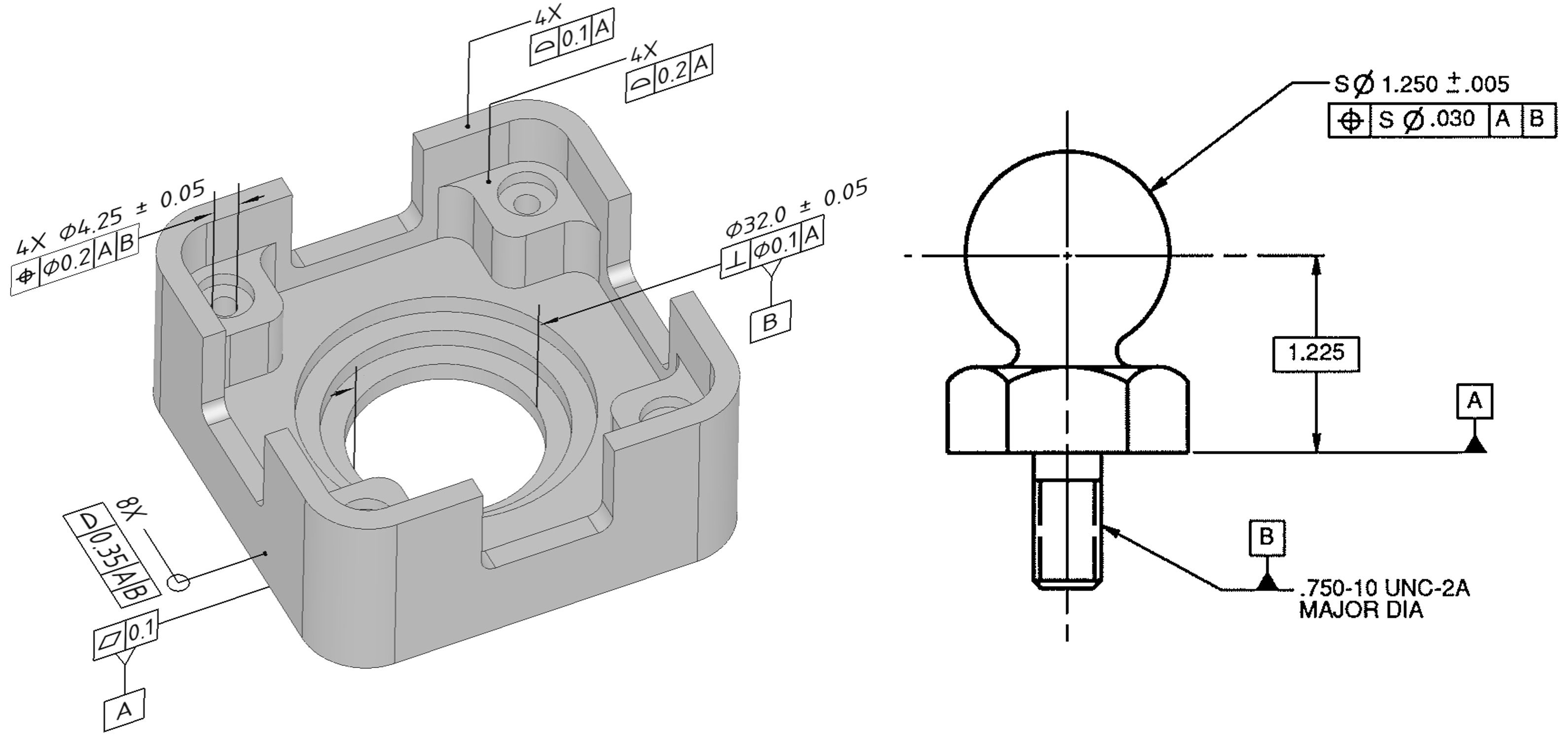
- This feature control frame specifies the positional tolerance zone as a circle of diameter .010 at MMC, centred according to the basic dimensions given.
- The tolerance zone's size depends on the size of the hole.
- MMC of hole = .250
- LMC of hole = .255
- Similarly, if Ⓛ symbol is used, the stated tolerance holds at least material condition (LMC). As the part departs from LMC, the amount of departure is added to the position tolerance.
- LMC is commonly used for loose fits.
- If no modifier is specified, (or ⓢ symbol in past practice) then the stated tolerance holds regardless of the material condition of the feature. This is called RFS – regardless of size.
- RFS is commonly used for pressed fits.
The logic behind bonus tolerances
- Taking an example for MMC

What is Composite Tolerancing?
- It can be used with profile and position tolerance.
- The symbol is entered once and is applicable to both horizontal entities.
- The upper segment controls location, orientation, form, and in some cases size.
- The lower segment controls mainly orientation and form. It does not control location.

Functional dimensioning philosophy
- Tolerance and tolerance zones based on part function and requirement
- Allows maximum tolerance to produce the part
- Functional dimensioning can often double or triple the amount of tolerance on many component dimensions, which reduces manufacturing costs

Above Fig. shows bolt holes for mounting a flange onto a plate (function). When mounting the flange, the position of the holes with respect to each other is important, or else the flange (or part) won’t fit. Functional dimensioning leads to dimensioning the distance between the holes, instead of the distances to the edge.
Round tolerance zones
- Four holes were drilled through the block (1), and each hole’s location relative to each other and the edges are specified using a limit tolerance of a distance and +.005 and -.005.
- The Center of each of the holes must fall within a square tolerance zone of .010 x .010 (2).
- Actual worst scenario is .014 or + .007 and -.007 (diameter)
- (3) Round tolerance zone over square tolerance zone for the part given in 1. Thus 57% increase in available tolerance.
- Resulting in more usable parts, more capable processes, reduced manufacturing costs

Bonus Tolerances using material condition modifiers
- In coordinate tolerancing, the tolerance zone is always fixed in size at all hole conditions.
- GD&T allows tolerance to be increased without compromising function. Parts that are functional are used, and more tolerance is allowed for production, resulting in lower operating costs.

Example explaining bonus tolerances
Created by - 3D SculpLab Team