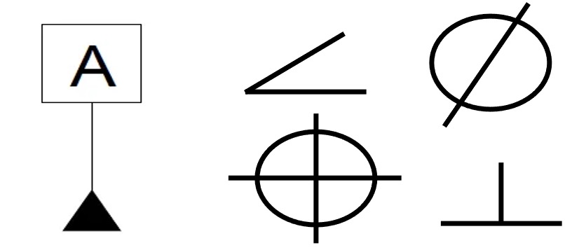
Symbols in GD&T
- GD&T has 14 geometric characteristic symbols.
- Various symbols used to specify tolerance zones are given below
- Form
- Position
- Profile
- Orientation
- Runout

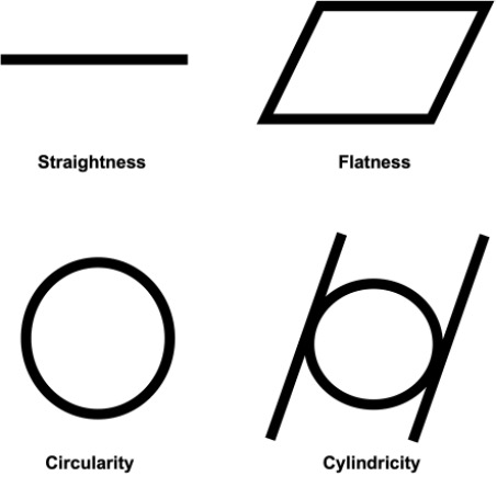
Straightness
Straightness describes a condition where an element of a surface or an axis is a straight line.

Flatness
Flatness is the condition of a surface having all elements in one plane.

The surface must lie between two planes 0.25 mm apart
Circularity
Circularity describes the condition on a surface of revolution (cylinder, cone, or sphere) where all points of the surface intersected by any plane (1) perpendicular to a common axis (cylinder, cone), or (2) passing through a common centre (sphere) are equidistant from the centre.

Each circular element of the surface in a plane perpendicular to the axis must lie between two concentric circles, one having a radius 0.25 mm larger than the other
Cylindricity
Cylindricity describes a condition of a surface of revolution in which all points of a surface are equidistant from a common axis.

The cylindrical surface must lie between two concentric cylinders one with a radius 0.25 mm larger than the other
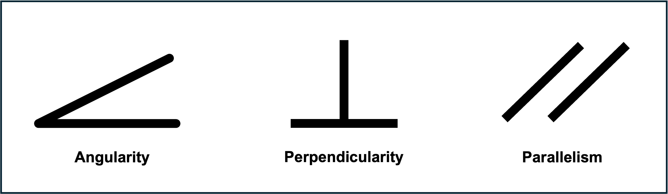
Parallelism
Parallelism is the condition of a surface, line, or axis, which is equidistant at all, points from a datum plane or axis.

1. The surface must lie between two parallel planes 0.12 mm apart, which are parallel to datum plane A.
2. The feature axis must lie within a 0.2 mm dia. of cylindrical zone parallel to datum axis A.
Perpendicularity
Perpendicularity is the condition of a surface, axis, or line, which is 90 deg. from a datum plane or a datum axis.

The feature axis must lie between two parallel planes 0.2 mm apart, perpendicular to datum axis A
Angularity
Angularity is the condition of a surface, axis, or centre plane, which is at a specified angle (other than 0˚, 90˚, 180˚ or 270˚) from a datum plane or axis.

The surface must lie between two parallel planes 0.4 mm apart inclined at an angle of 300 to datum plane A
Profile of a surface
Profile of a surface is the condition permitting a uniform amount of profile variation, either unilaterally or bilaterally, on a surface.

Profile of a line
Profile of a line is the condition permitting a uniform amount of profile variation, either unilaterally or bilaterally, along a line element of a feature.

The profile of a line is used in conjunction with the profile of the surface. The profile of a surface defines the shape or location of a feature while the profile of a line refines it in one direction. Each line element of the surface must lie between two profile boundaries 0.006 mm apart in relation to the datum reference frame
Circular runout
Circular runout gives the deviation from the desired form of a circular element of a part surface of revolution through one full rotation (360 deg) of the part on a datum axis. Circular runout controls the circular elements of the surface, not the complete surface.

At any position, each circular element of the surface must be within the specified runout tolerance (0.02 mm full indicator movement) when the part is rotated by 3600, about the datum axis, the indicator fixed in a position normal to the true geometric shape
Total runout
Total runout is the simultaneous composite control of all elements of a surface at all circular and profile measuring positions as the part is rotated through 360.

The entire surface must lie within the specified runout tolerance zone (0.02 mm full indicator movement) when the part is rotated by 3600 about datum axis A, with the indicator at every location along the surface in a position normal to the true geometric shape without reset of the indicator.
Concentricity
Concentricity describes a condition in which two or more features (cylinders, cones, spheres, etc.) Any combination has a common axis.

This controls the location and can have some effect on the form and orientation of a feature. The application of concentricity is complex and rare. Diametrically opposed dial indicators may be used to check this.
Symmetry
Symmetry is a condition in which a feature (or features) is symmetrically disposed about the centre plane of a datum feature.

Controls opposing points (that form derived median plane). The same concept as concentricity but applied to non-cylindrical features.
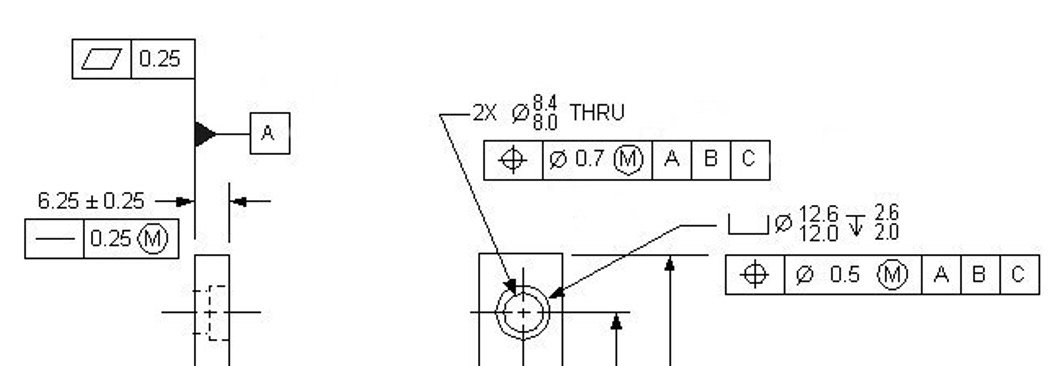
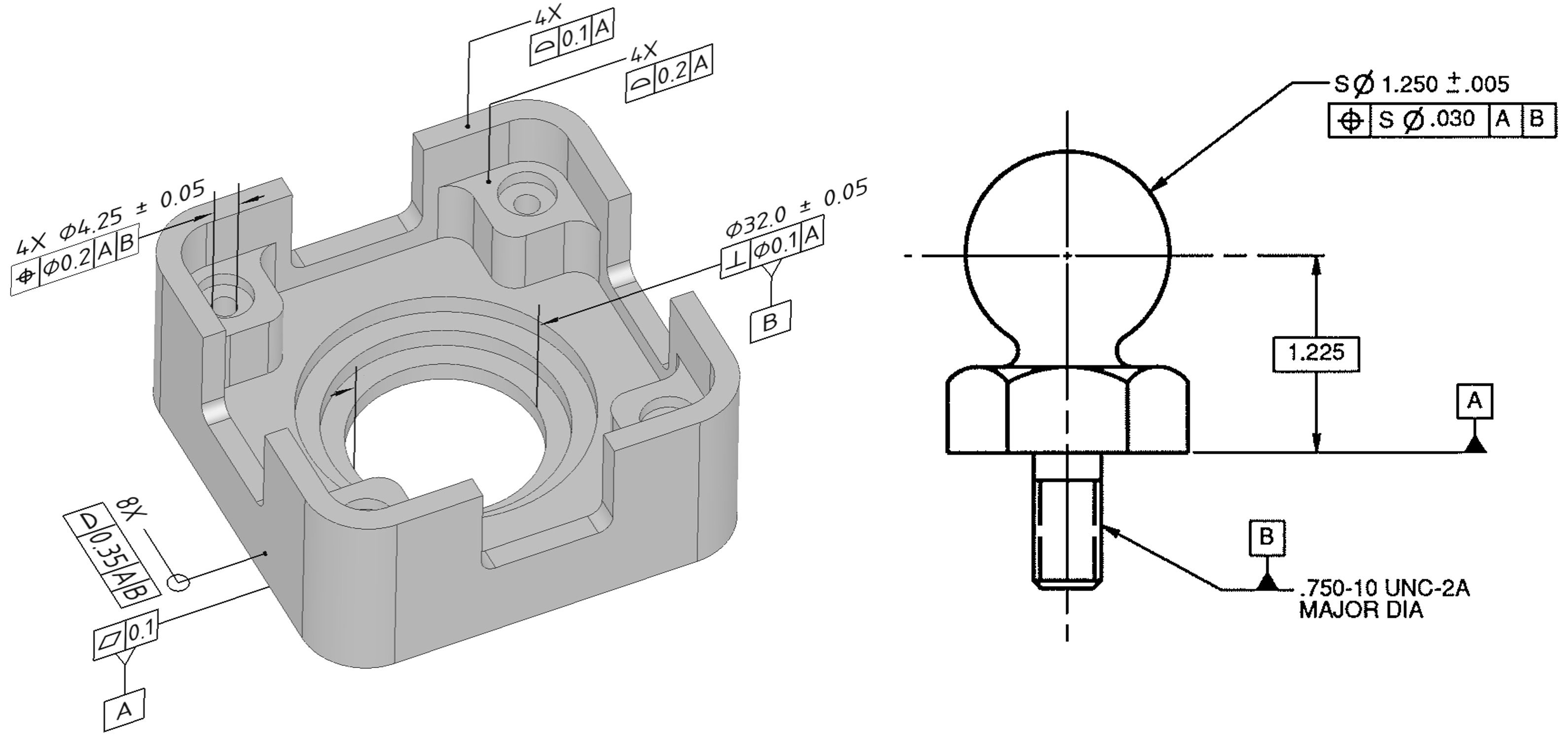
Position
Position tolerance (formerly called true position tolerance) defines a zone within which the axis or centre plane of a feature is permitted to vary from the true (theoretically exact) position.

- Position tolerancing is used to locate features of size.
- These tolerance zones can be cylindrical, conical, rectangular, etc.
- The profile is used to locate features that don’t have a size associated with them
- Defines a zone within which, the axis, median plane, or surface of a feature is permitted to lie
Created by - 3D SculpLab Team