For more information about our services reach us at: +91-7975944394 & create@3dsculplab.xyz
FFF/FDM Design Guidelines
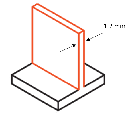
Minimum wall thickness
Wall thicknesses (including ribs) are critical because the low resolution print will often fail if it does not have a strong supporting layer. For this reason recommends at least 1.2mm or more for better results.
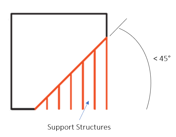
Minimum angle to avoid support
Design feature/surface can self support up to 45° of angle. Angle falling below 45° needs supports to generate surfaces. You’ll want to avoid this because not only does support material add cost, but it creates a rough surface finish after supports are removed.
0.4mm clearance for connecting or moving Parts
Clearance is necessary for any mating/sliding parts. You never want to design a 10mm shaft for a 10mm hole. We recommend a total 0.4mm clearance. For a cylinder, this is a 0.2mm gap all the way around, or 0.2mm gap on each side of a square.
Embossing & Engraving
Text layout should be about 2mm high (for embossing) / deep(for engraving) & 1.4mm wide and use at least a 16 point bold font to ensure that label prints clearly.
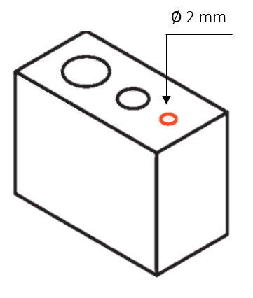
Holes
Minimum recommended hole diameter is 2mm. Add additional 0.4mm to all the hole diameters to compensate for hole shrinkage in x and y directions.
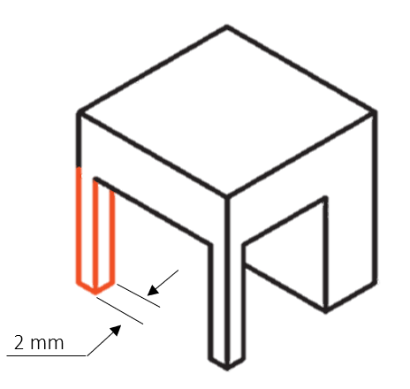
Features
The recommended 2mm minimum size of a feature to ensure it will not fail.
Pin diameter
Minimum recommended pin diameter is 3mm & height should be 3x of diameter.
Tolerance
The tolerance of the FFF printed part will be around ± 0.5mm. Tolerance may vary depending upon the shrinkage factor effected by the design & material volume. Shrinkage usually happens in the range of 0.2 - 1% depending on type of material.
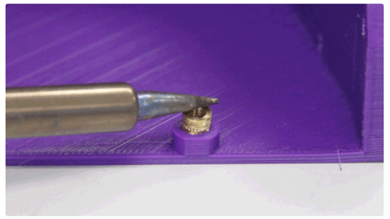
Threading Insert
Design the hole to the smallest tapered hole diameter and design the walls around the insert to be at least 2mm thick.
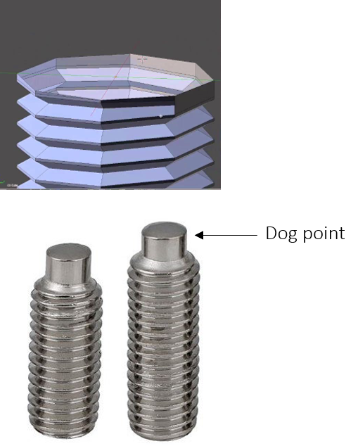
Threads
Avoid sharp edges when designing built-in threads. Instead, go for rounded crests and roots. In plastic parts, sharp edges are stress concentrators.
A dog point screw features a flat, unthreaded tip that stretches from one end of the screw. This tip is helpful for locating a groove on a shaft. Note that it should be at least 1~2 mm in length.
Smaller threads are difficult to print and are not recommended for FFF/FDM process, particularly if the threaded part needs to go into a hole with a diameter of 2 mm or less. An easy alternative is to use a tap (or a die) to make smaller threads.
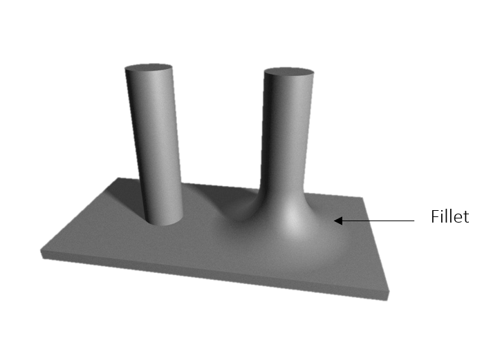
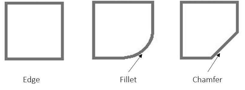
Add fillets
The primary use case for fillets is to strengthen fragile protruding features. Without additional support around their bases, these structures are liable to snap off, even during printing.
Fillets are useful for reducing stress concentrations and increasing the overall strength of the 3D printed part. When you introduce fillets, maintaining consistent thickness on the print is critical.
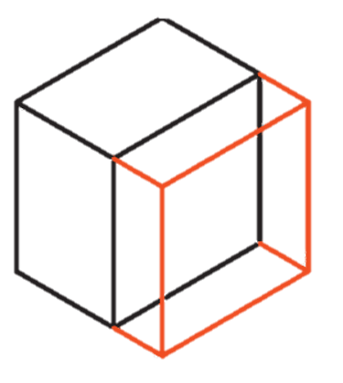
Add chamfers or fillets to the bottom edge’s
It is recommended to add a chamfer or a fillet to the bottom edges (surface touching build plate) of your design. This will reduce the chances of print defects/fail.